Istanbul Studio ARCH 916 5th Year Fall 2011 Professor Weldon Pries
Pre-Final Review on December 1, 2011 and
Final Presentation Review on December 8, 2011
Drawings Due: December 7, 2011 Wednesday
MODELS
1. Small Massing Model
• Model to be placed into the site model.
• Include a series of alternate massing models.
2. Massing Model of project and surrounding city buildings: Scale 1”=50’ or 1”=32’
• Show major exterior spaces, roof forms, areas of glazing, major structure if applicable.
3. Building Complex Model: Scale 1”=16’ 1”=32’ or as required
• Model indicating massing, volumetric elements, structural system, glazing, exterior building surfaces, and architectural details. Show major interior spaces.
DRAWINGS: All drawings to be printed and plotted (without tiling) on 30 x 40 approx. sheet format. All drawings to be rendered to show important analytical emphasis.
4. Site Plan(s): Scale 1”=500’ (Golden Horn) AND 1”=200’ (City area with your site)
• Plan of the building complex with indication of street, architectonics, figure ground, street design elements, spatial configurations, and contextual information.
5. Roof plan: Scale 1”=100’ rendered to show project roofs, exterior space designs, and significant existing city reference features of streets, exterior spaces, monuments, and Golden Horn.
6. Building Plans: Scale 1”=32’ or 1”=16’
• A: First (Ground) Floor Plan showing major interior space, structure, urban spaces and adjacent buildings.
• B: Upper Level Plans: Second Floor Plan or major spaces and uses related to first floor plan.
• C: Additional plan of typical residential floor and/or major uses
7. Sections: Scale 1”=16’
• 2 Sections though building complex showing major spatial and structural systems, major architectural detail, and elevations beyond the section cuts. Include urban spaces and adjacent buildings.
8. Elevation(s): Scale: 1”=16’
• Building street elevation with adjacent buildings
9. Perspective Drawings:
• One or two perspective drawings showing the buildings and urban spaces with architectonic detail within the context of the adjacent buildings or site.
10. 4 rendered aerial perspectives showing your project in relationship to the adjacent contect.
11. Optional:
• Section with architectonic details; Scale: ¼” = 1’-0” or ½” = 1’-0”
• Large scale Section/Elevation or Section/Perspective – location at important intersection or urban space and interior space. Include all technical details of structure, fenestration, cladding and design details.
STATEMENT
12. Written statement:
• One or two pages (300-400 words), including design concept, concept in relationship to the city, analysis of project as urban design, building complex design, and building program.
http://myweb.wit.edu/priesw/Istanbul_2011/index.html
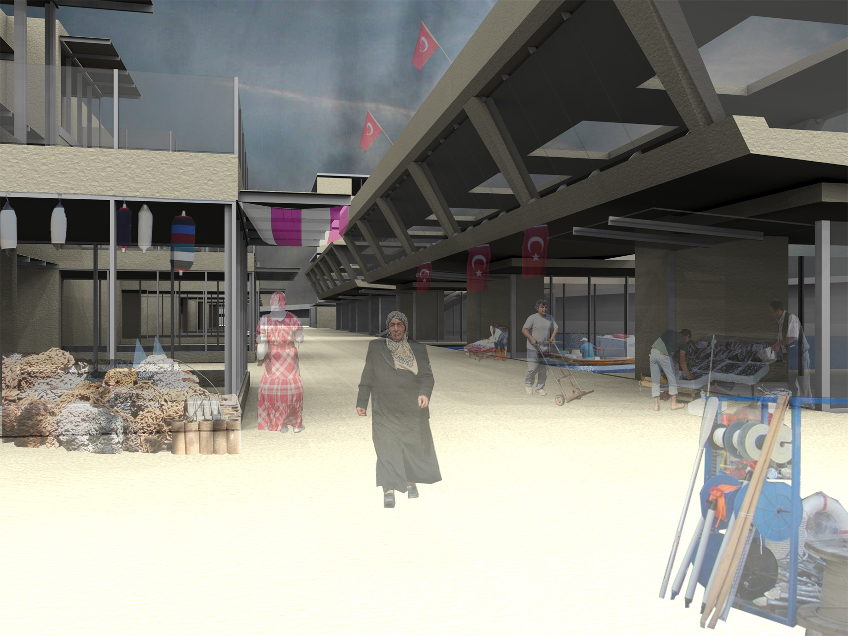
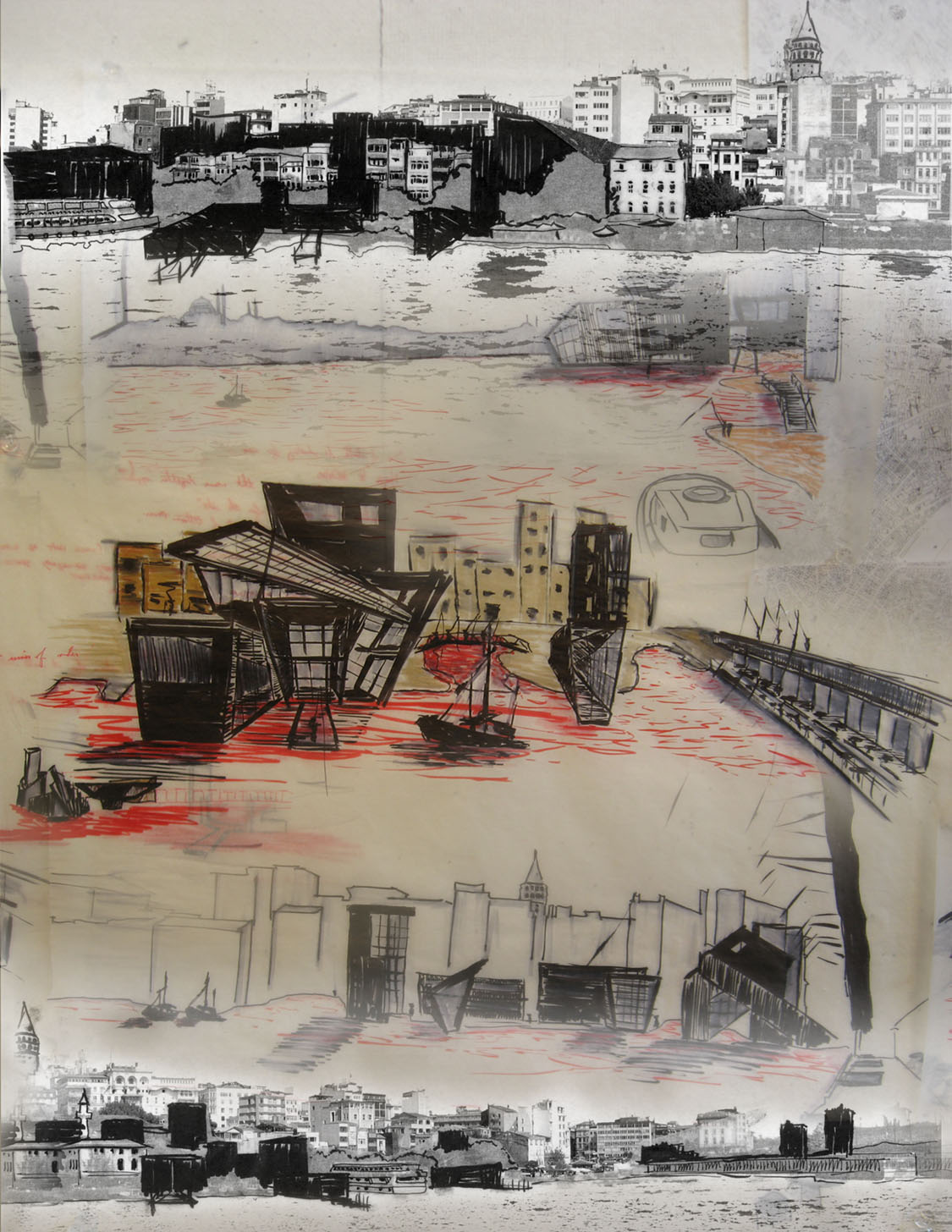
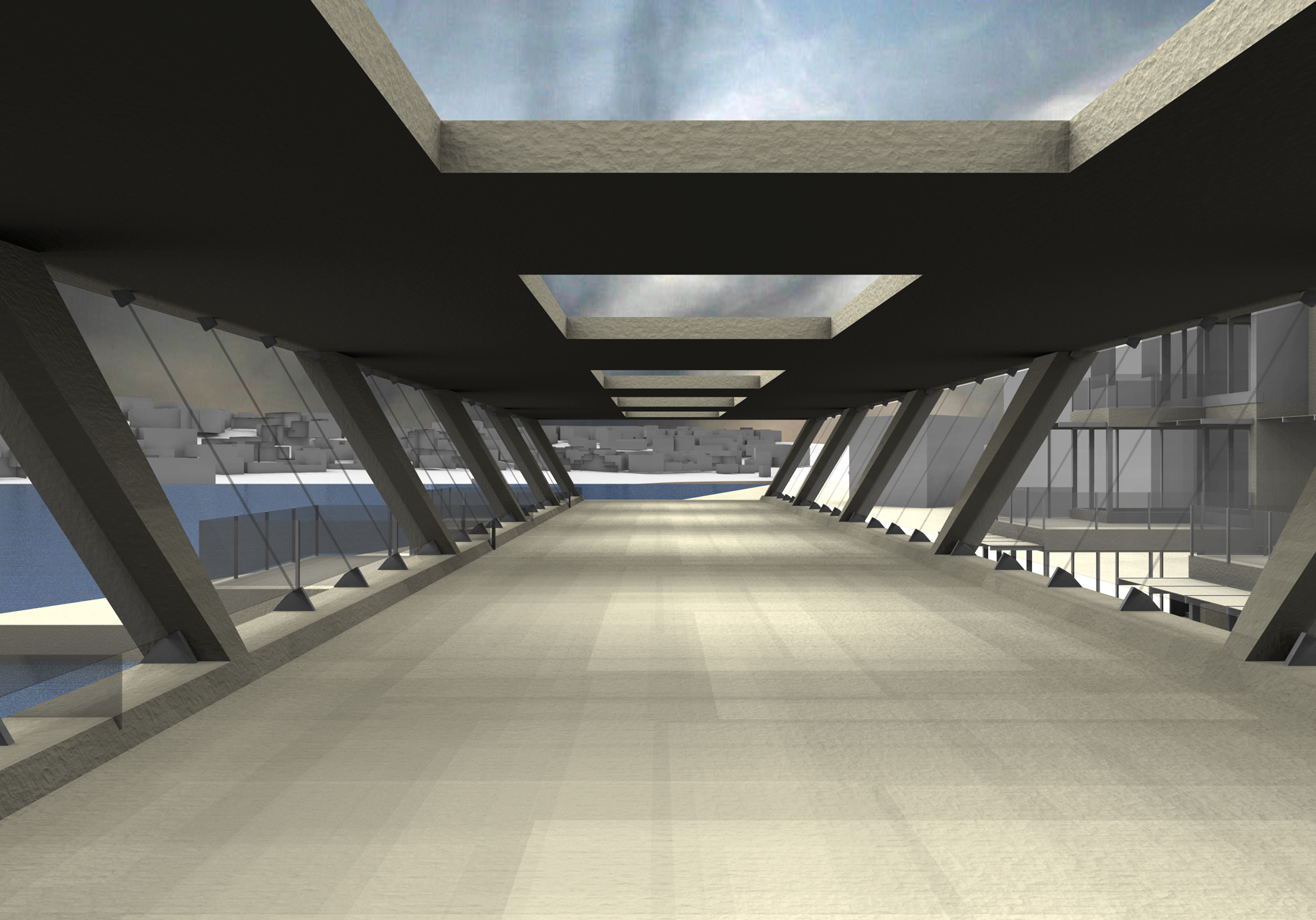
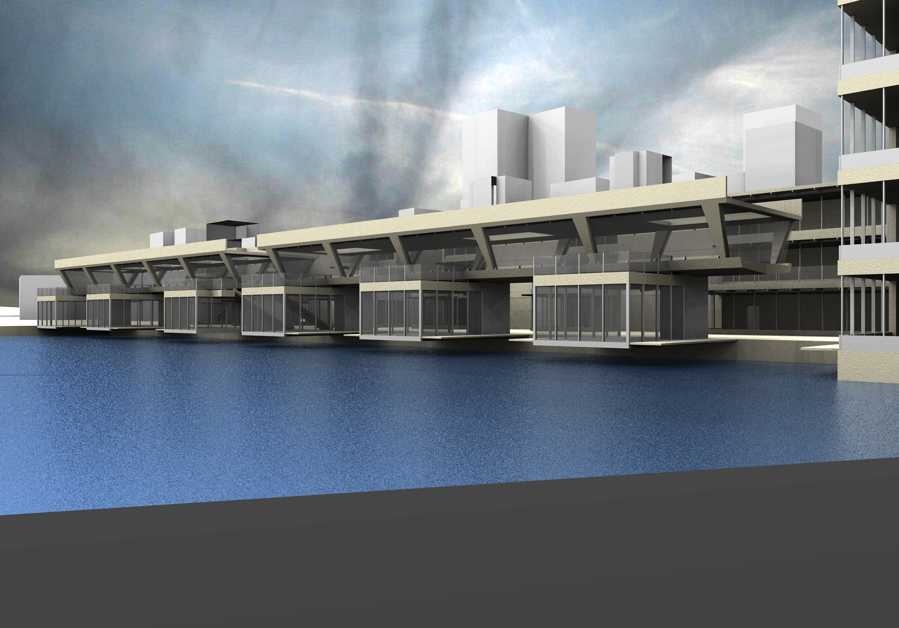
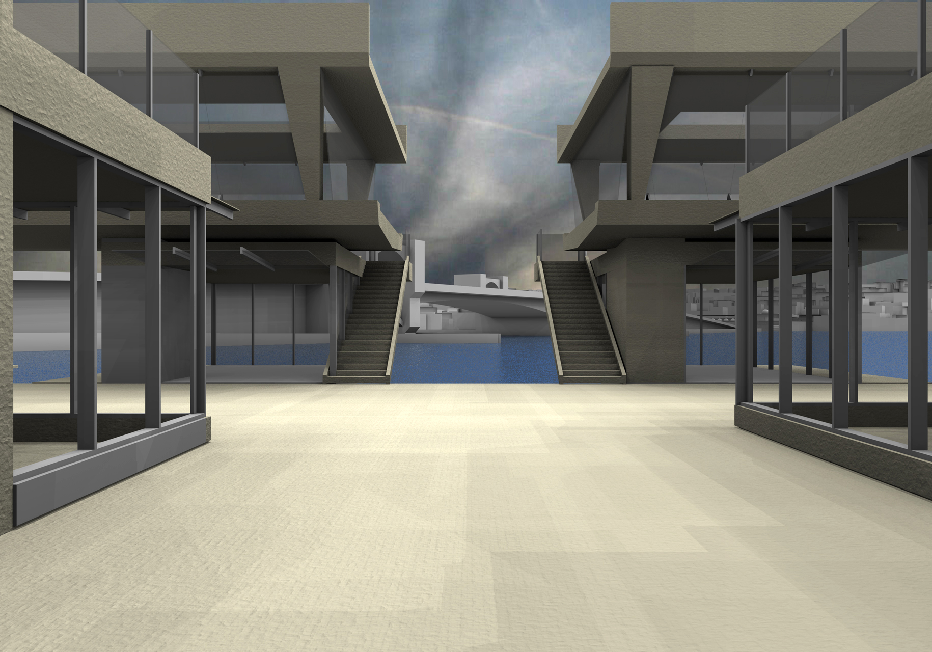
In Beyoglu along the Golden Horn, there is a clear distinction between the long established edge of the shoreline and the additional infill later added to accommodate a green area along the waterfront. My concept emphasizes the contrast between the original and present-day shorelines in the area along the fish market. It pulls back toward the original shoreline, reinforces that edge with orderly program, and adds a layer of ambiguity beyond reaching out toward the water to mirror the fragmentation of the present shoreline. Relating to Ambiguous Spaces, a layer of infrastructure was introduced that changed the relationship people had with the waterfront.